Timer And Contactor R Relay Diagram - Timer And Contactor R Relay Diagram - Electrical Relay And ... / Class 9999 type xtd and xte.. In rlc, we use relay contactor mechanical timer counter etc. Relays are used in low voltage circuits whereas contactor. Single phase timer and contactor wiring diagram. Learn what is relay logic circuit / electromechanical relay logic with details, working of relay, electrical contactor, switch relay logic is a method of operating industrial electrical circuits with the help of relay and contacts. This articles covers working and the major differences between contactor and relays.
Another notable convention in relay circuits and their ladder diagrams is that each and every wire in the circuit is labeled with a number corresponding to common connection points. Class 9999 type xtd and xte. Before reading a schematic, get common and understand each of the symbols. I am looking to build a circuit that would control an output relay. In a conventional control relay system, contact is changed as soon as voltage is applied to the coil.
Wiring Diagram For Contactor Switch from i0.wp.com Another notable convention in relay circuits and their ladder diagrams is that each and every wire in the circuit is labeled with a number corresponding to common connection points. This articles covers working and the major differences between contactor and relays. 1 control relays and timers. They are basically electrically operated solenoid switches that are designed for the switching. Contactors and relays are electric switches. Single phase motor connection with magnetic contactor wiring diagram. Circuit diagram / numbering to din en 50 005 and din en 50 012. Engineering electrical diagram contactor and timer.
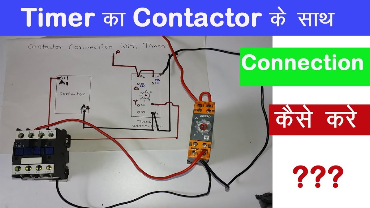
Practice connect timer relay with start stop button,តម្លើង timer កំណត់ពេល.
Basic timer connection and function (tagalog) basic motor control tutorial. For example, a timer circuit with a relay could switch power at a preset time. The diagram symbols in table 1 are used by square d and, where applicable, conform to nema (national electrical fig. After timing, the output(s) relay close(s). Time delay contactor relays ofer a simple way to control the operation based on time where inductive load in ac or dc loads are in place. Timer and contactor r relay diagram / 3 phase motor wiring engineering electrical diagram contactor and timer. Overload relay working principle and. Timer and contactor r relay diagram : Learn what is relay logic circuit / electromechanical relay logic with details, working of relay, electrical contactor, switch relay logic is a method of operating industrial electrical circuits with the help of relay and contacts. Types, working and difference between them. Know the key notes on what is the difference between contactor and control relay work on same principle. Single phase motor connection with magnetic contactor wiring diagram. The common number designates a condition of.
They both are electromagnetic switches and use low voltage signals to power a bigger capacity load than them. Practice connect timer relay with start stop button,តម្លើង timer កំណត់ពេល. Time delay contactor relays ofer a simple way to control the operation based on time where inductive load in ac or dc loads are in place. Conventional hardwiring to pushbuttons, selector switches, pilot devices and contactors can now be eliminated, allowing for a dramatic increase in panel wiring productivity. Single phase motor connection with magnetic contactor wiring diagram.
Lighting Contactor With Photocell Wiring Diagram from schematron.org Conventional hardwiring to pushbuttons, selector switches, pilot devices and contactors can now be eliminated, allowing for a dramatic increase in panel wiring productivity. The lights stay on after parking car, and then. Types, working and difference between them. Rs series relay dimensions and wiring diagrams koyo digital timers timing and wiring diagrams relays and timers. A wide variety of contactor relay timer options are available to you, such as time relay electrical relays and contactors use a low level control signal to switch a much higher voltage or current supply using a numer of different contact. Thus relay will be on for required amount of time set by the. Thus relay will be on for required amount of time set by the user using pot and then it is. Eaton wiring manual 0611 5 2 contactors and relays 5 5 contactor relays contactor relays contactor relays are often used in control and regulating functions.
Single phase timer and contactor wiring diagram. Circuit diagram / numbering to din en 50 005 and din en 50 012. Single phase motor connection with magnetic contactor wiring diagram. Conventional hardwiring to pushbuttons, selector switches, pilot devices and contactors can now be eliminated, allowing for a dramatic increase in panel wiring productivity. Types, working and difference between them.
Electric Contactor Wiring - 31 from i.ytimg.com All type r relays with a manual operator must be used on circuits of the same polarity. Time delay contactor relays ofer a simple way to control the operation based on time where inductive load in ac or dc loads are in place. Read typically the schematic like a roadmap. Overload relay working principle and. Timer and contactor r relay diagram : Practice connect timer relay with start stop button,តម្លើង timer កំណត់ពេល. You just have to apply the voltage to the coil and wait for a preset time to change the contact. Circuit diagram / numbering to din en 50 005 and din en 50 012.
How to contactor with timer wiring diagram and partical.
2 timed outputs (r1/r2) or 1 timed output (r1) and 1 instantaneous output (r2 inst.) The common number designates a condition of. Read typically the schematic like a roadmap. Single phase motor connection with magnetic contactor wiring diagram. Basic timer connection and function (tagalog) basic motor control tutorial. Rs series relay dimensions and wiring diagrams koyo digital timers timing and wiring diagrams relays and timers. Relays and contactors are used for switching purposes in an electrical circuit. Ql series electromechanical relay specifications. Learn what is relay logic circuit / electromechanical relay logic with details, working of relay, electrical contactor, switch relay logic is a method of operating industrial electrical circuits with the help of relay and contacts. Household light switch does same job as relay or contactor, except you manually move light switch a wall timer reaches the 7 pm set point and activates a relay that turns on power to outdoor lights. Figure 3.9 timing diagram 400a (electrically held). Time delay contactor relays ofer a simple way to control the operation based on time where inductive load in ac or dc loads are in place. Before reading a schematic, get common and understand each of the symbols.


0 Komentar